
The most common civil engineering soil test failures are inadequate site characterization, insufficient borehole density, disturbed or mislabeled samples, wrong test selection for the soil type, compaction acceptance that misses long-term hydrocollapse, masked groundwater readings, contamination screening gaps, and overlooked liquefaction or frost susceptibility. Each of these failures produces a flawed geotechnical model, and a flawed model drives unsafe or wasteful foundation design.
When any of these failures are suspected, the immediate triage sequence is:
- Stop the design freeze until the geotechnical basis is confirmed adequate.
- Request clarifying data from the geotechnical consultant, specifying which tests or borings are missing.
- Install monitoring where groundwater or settlement behavior is uncertain: piezometers for water table, settlement plates for compressible zones.
- Issue a formal RFI to the geotechnical consultant documenting the data gap and the required response.
In the United States, inadequate site characterization is consistently identified as the top root cause of geotechnical failures, producing faulty geological models and poor design outcomes. The FHWA and ASTM both provide test-specific guidance that project teams should reference before accepting any geotechnical report. The single most protective action a project team can take is to require a phased, iterative investigation with explicit contingency borings written into the scope of work before mobilization begins.
Table of Contents
- What actually goes wrong in soil testing and site investigation
- Why too few or poorly placed borings break designs
- How lab errors and calibration failures corrupt soil parameters
- Why compaction acceptance on paper can still fail in service
- What soil test failures actually cause on site, schedule, and budget
- What to specify in the SOW and how to run QA/QC on a geotechnical program
- What to demand from a geotechnical report before accepting it
- The three-stage misinterpretation pathway and lab QA/QC best practices
- Key Takeaways
- Why rigorous investigation is the only cost-effective path
- Aectechnicalsg: geotechnical consultancy for projects that cannot afford a failed soil test
- Useful sources and standards for geotechnical specification and QA/QC
What actually goes wrong in soil testing and site investigation
Understanding the full inventory of common civil engineering soil test failures requires looking at both field and laboratory stages. The table below maps each failure type to its primary diagnostic test and the typical false reading or miss it produces.
| Failure Type | Primary Diagnostic Test(s) | Typical False Reading or Miss |
|---|---|---|
| Inadequate site characterization | SPT/CPT, geophysics | Missed weak layers, undetected fill zones |
| Insufficient borehole density | SPT, CPT | Lateral variability undetected between borings |
| Disturbed samples | Triaxial, consolidation | Overestimated strength, underestimated compressibility |
| Wrong test selection | Atterberg limits, triaxial | Index tests only; long-term strength not assessed |
| Lab analytical errors | All quantitative tests | Incorrect parameters fed to structural design |
| Compaction acceptance pitfall | Moisture-density (ASTM D1557) | Passes short-term; hydrocollapse on wetting |
| Masked groundwater reading | Piezometer, standpipe | Single-event reading misses seasonal high |
| Contamination screening miss | Phase I/II, chemical analysis | Reactive soils or contaminants undetected |
| Liquefaction/frost oversight | CPT, grain size, Atterberg limits | Seismic or freeze-thaw vulnerability unrecognized |

Inadequate site characterization shows up in reports as unexplained lateral variability in SPT N-values, missing data near key load points, or a geological model built from too few data points. Disturbed samples are a subtler problem: remolding during sampling reduces apparent cohesion and alters moisture content, so triaxial and consolidation tests on those samples overstate strength and understate settlement. The specific impact depends on how severely the sample was remolded and whether moisture was gained or lost during handling.
Wrong test selection is common on projects where budget pressure limits the program to index tests only. Atterberg limits and moisture content identify soil classification, but they cannot predict long-term consolidation behavior or drained shear strength for critical structures. Triaxial and consolidation tests are required when settlement sensitivity or slope stability is a design driver. Many reports also publish SPT N-values without correlating them to shear strength or consolidation parameters, forcing structural designers to adopt conservative values that can produce inefficient or unsafe designs.
Why too few or poorly placed borings break designs
Site investigation planning is where most geotechnical failures originate. A stepwise investigation assumes a working geological model, plans targeted borings to test that model, then re-interprets and expands the program if the data contradicts the assumption. Skipping the re-interpretation step is the most common planning failure.
Borehole locations biased toward accessible areas, rather than aligned to the structure’s load footprint, produce a dataset that looks complete on paper but misses the critical zones. Known hazard areas near waterways, historic fills, or former landfills require deliberate targeting. When borings are placed for convenience rather than geological logic, the resulting model carries hidden uncertainty that only surfaces during construction or, worse, after handover.
Key insight: Geotechnical engineers sometimes prioritize budget and schedule over reducing geological uncertainty. Building explicit contractual steps that force iterative interpretation and contingency borings is the most reliable safeguard against this pressure. (Source)
Signs of inadequate sampling that warrant supplemental borings:
- Inconsistent SPT or CPT trends between adjacent borings with no geological explanation.
- No borings within the footprint of the heaviest loaded structural elements.
- Absence of piezometer installations or long-term groundwater monitoring recommendations.
- Boring depths that terminate above the expected zone of influence for the proposed foundation.
- No data from areas identified in historical records as fill, disturbed ground, or former water features.
- Lateral variability in soil classification that the report does not explain with a geological model.
For geotechnical investigation planning, minimum boring density should be tied explicitly to the structure’s footprint dimensions and load distribution, not to a flat spacing rule applied uniformly across the site.
How lab errors and calibration failures corrupt soil parameters
Laboratory errors translate directly into unreliable design parameters. The most common lab-side failures fall into four categories: method misuse, instrument calibration lapses, data entry errors, and inappropriate correlations between index tests and strength parameters.
Method misuse occurs when a test procedure is applied outside its validated context. A well-documented example is using an extractant method on a soil type for which it was not calibrated, producing false interpretations that cannot be detected without independent verification. Calibration lapses are equally damaging: a load cell or displacement transducer that has drifted from its calibration baseline will produce systematically biased consolidation or triaxial results across every test run on that instrument. Calibration schedules for load cells, pressure transducers, and displacement gauges should be documented in the lab annex of every geotechnical report.
Data entry and transcription errors are underappreciated. Large soil-test datasets have shown duplicate records and out-of-range values that distort statistical summaries and management recommendations. Chain-of-custody documentation and digital QA checks at the point of data entry are the practical controls.
Best practice: Require the laboratory to document the calibration date and certificate number for every instrument used, and include that record in the factual report annex. Any instrument without a current calibration certificate should disqualify those test results from use in design.
Pro Tip: When contracting laboratory services, include a SOW clause requiring blind and double-blind samples at a defined frequency, periodic proficiency testing against a reference laboratory, and a written method-selection justification for every test type. Request these as deliverables in the lab annex, not as verbal assurances.
Blind and double-blind samples detect systematic analytical bias early, before those biased parameters reach the design team. For high-risk projects, periodic proficiency reporting against an independent reference lab is the standard of care.
Why compaction acceptance on paper can still fail in service
Passing a short-term compaction test does not guarantee long-term field performance. Standard acceptance testing, typically relative compaction against ASTM D1557 (Modified Proctor), measures density and moisture at the time of placement. It does not measure the soil’s response to wetting after placement, which is the mechanism behind hydrocollapse.
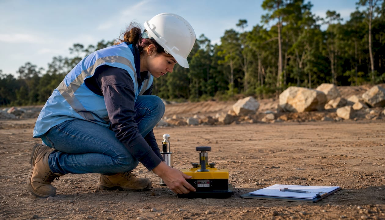
Deep compacted fills have sometimes exhibited substantial hydrocollapse settlement in canyon fills exceeding certain depths, even when those fills passed standard compaction acceptance at the time of construction. The fills met the specified relative compaction, but were placed on the dry side of optimum moisture. Meniscus forces between particles created a metastable fabric that collapsed when the fill was later wetted by irrigation, rainfall infiltration, or rising groundwater.
| Acceptance Method | What It Measures | What It Misses |
|---|---|---|
| Relative compaction (ASTM D1557) | Density at placement | Post-wetting volume change |
| Moisture-density relationship | Optimum moisture at compaction | Seasonal moisture variation in service |
| Nuclear gauge field test | In-place density and moisture | Long-term consolidation under load |
| Plate load test | Immediate bearing response | Creep and saturation-induced settlement |
Documented consequence: Canyon fills over 20 feet deep have exhibited up to 18 inches of settlement on re-wetting, despite passing short-term compaction acceptance. This is not a rare edge case; it is a predictable outcome when fills are placed dry of optimum without post-construction moisture monitoring. (Caltrans guidance)
Mitigation requires moisture conditioning protocols that bring fill material to within a specified range of optimum before compaction, staged fill placement with settlement monitoring between lifts, higher compaction thresholds for fills exceeding a defined depth, and performance monitoring instruments left in place through the first wet season. For projects with earthworks failure risk, these controls should be contractual requirements, not optional enhancements.
What soil test failures actually cause on site, schedule, and budget
The consequences of failed or inadequate soil testing are concrete and measurable. Excessive settlement is the most common outcome, ranging from cosmetic cracking in slabs to structural distress in foundations. Differential settlement, where one part of a structure settles more than another, causes frame distortion, door and window binding, and in severe cases, structural instability.
Bearing capacity failures occur when design parameters derived from inadequate testing overestimate the soil’s actual load-carrying ability. The result is foundation movement, column distress, or in extreme cases, sudden bearing failure requiring emergency underpinning. Slope instability triggered by undetected weak layers or rising groundwater has caused retaining wall failures and embankment collapses on projects where the geotechnical model was built from insufficient data.
- Excessive settlement: Slab cracking, utility line damage, pavement rutting, and structural distress.
- Differential movement: Frame distortion, façade cracking, and serviceability failures in sensitive structures.
- Bearing capacity loss: Foundation movement requiring costly underpinning or redesign.
- Pavement cracking: Premature surface depressions and rutting from undetected compressible or expansive subgrade.
- Slope instability: Retaining wall failure or embankment collapse from missed weak layers.
- Dewatering and redesign delays: Undetected groundwater triggers redesign of excavation support and dewatering systems, adding weeks to the program.
Ambiguous or overly conservative geotechnical data drives overdesign. When SPT values are reported without derived strength parameters, structural designers default to conservative assumptions that increase pile lengths, foundation depths, or reinforcement quantities beyond what the actual soil conditions require. The cost of supplemental investigation is almost always lower than the cost of overdesign or construction rework. Decision points for pausing foundation design and requiring additional testing include: unexplained variability between borings, groundwater readings that conflict with regional data, and any indication of fill, organic material, or contamination in the zone of influence. Lateral soil resistance uncertainty also affects structural design; lateral load distribution assumptions built on unreliable passive pressure parameters can drive overdesign of retaining elements and pile caps.
Specialist consultation triggers include: liquefaction potential on seismic sites where CPT data shows susceptible grain sizes, contamination findings that require a Phase II environmental site assessment, and any site with organic soils, karst, or historic fill requiring a dedicated settlement analysis.
What to specify in the SOW and how to run QA/QC on a geotechnical program
A well-written scope of work is the primary tool for preventing the failures described above. The following SOW items address the most common gaps.
- Minimum boring density tied explicitly to the structure’s footprint dimensions and load distribution.
- Requirement for undisturbed tube sampling (Shelby tubes or equivalent) where triaxial or consolidation testing is planned.
- Specified lab test suite: index tests plus triaxial (UU and CU) and consolidation tests for settlement-sensitive or critical structures.
- Blind QC samples at a defined frequency, with proficiency reporting against a reference laboratory.
- Piezometer installations at locations identified as groundwater-sensitive, with monitoring through at least one seasonal cycle.
- Required deliverable: a documented geological interpretation model, not just a factual data report.
- Contingency boring allowance: a defined number of additional borings triggered by specified data conditions (e.g., unexplained variability, fill encountered).
For geotechnical instrumentation selection and placement, piezometers and settlement plates should remain in place through key construction milestones, not just through the investigation phase.
Timeline and cost expectations for a typical site investigation package:
| Investigation Scale | Typical Mobilization | Borings and Field Work | Lab Turnaround | Report Delivery |
|---|---|---|---|---|
| Small footprint | 1–2 weeks | 3–5 days | 2–3 weeks | 1–2 weeks after lab |
| Medium footprint | 2–3 weeks | 1–2 weeks | 3–4 weeks | 2–3 weeks after lab |
| Large footprint (over 5 acres) | 3–4 weeks | 2–4 weeks | 4–6 weeks | 3–4 weeks after lab |
Cost ranges are not publicly standardized and vary significantly by region, soil complexity, and test suite. Project teams should budget for supplemental investigation contingency of at least 15–20% of the base investigation cost on sites with known geological complexity.
Sample RFI language for procurement documents: “The geotechnical report shall include derived shear strength and consolidation parameters from site-specific triaxial and consolidation testing, with the correlation method and hammer efficiency corrections documented for all SPT-based correlations. Groundwater levels shall be confirmed by piezometer monitoring over a minimum of one seasonal cycle.”
What to demand from a geotechnical report before accepting it
Before accepting a geotechnical report and proceeding to foundation design, the project team should verify the following:
- Boring locations are shown on a plan keyed to the structure’s footprint, with at least one boring within the zone of influence of each major loaded element.
- Boring depths extend below the full zone of influence for the proposed foundation type and load magnitude.
- Undisturbed samples are documented for any zone where triaxial or consolidation testing is required.
- Lab test suite includes index tests plus triaxial and consolidation tests for settlement-sensitive or critical structures; index tests alone are insufficient for these cases.
- Groundwater monitoring is addressed either by piezometer data covering a seasonal cycle or by an explicit statement of the limitations of single-event readings.
- QA/QC evidence is present: blind sample results, lab accreditation certificate, and calibration records for key instruments.
- Bearing capacity recommendations are given for both shallow and deep foundation options, with explicit assumptions stated.
- Limitations and assumptions are documented, including areas of the site not investigated and conditions that could alter the conclusions.
Immediate red flags that must be resolved before structural design proceeds: no borings within the loaded footprint, groundwater data from a single drilling event only, SPT values reported without derived strength parameters, no mention of collapsible or expansive soil potential in regions where these are known to occur, and absence of any QA/QC documentation.
The three-stage misinterpretation pathway and lab QA/QC best practices
Geotechnical failures rarely originate from a single error. Misinterpretation typically occurs across three stages: geological model creation, geotechnical modeling, and civil or structural design. An error introduced at the first stage propagates and amplifies through each subsequent stage, so that by the time it reaches the structural designer, the original data gap has become a compounded design assumption.
At the geological modeling stage, the failure is usually building a model directly from raw borehole data without a documented geological interpretation step. Require a written geological interpretation in the geotechnical scope, with peer review when site complexity or uncertainty is high. At the geotechnical modeling stage, the failure is using raw SPT N-values without corrections for hammer efficiency, overburden, and borehole diameter, then applying empirical correlations outside their validated range. At the structural design stage, the failure is accepting conservative default parameters without questioning whether the investigation was sufficient to support those parameters.
Research finding: A non-obvious pitfall is building geotechnical models directly from raw data without geological interpretation. Requiring a documented geological interpretation step, with peer review when uncertainty is high, is the most effective single intervention at the modeling stage. (Source)
Recommended lab QA/QC protocol checklist:
| QA/QC Element | Frequency | Deliverable |
|---|---|---|
| Blind samples submitted | Every 10–20 samples | Blind sample results in lab annex |
| Instrument calibration check | Per manufacturer schedule | Calibration certificate in report |
| Proficiency testing vs. reference lab | Annually or per project | Proficiency report |
| Chain-of-custody documentation | Every sample | Signed chain-of-custody form |
| Method selection justification | Per test type | Written method rationale in SOW |
| Cross-check field logs vs. lab results | Before report issue | Discrepancy log in report |
Key Takeaways
Soil test failures are preventable when the scope of work, sampling plan, and lab QA/QC protocols are specified contractually before mobilization, and when the geotechnical report is reviewed against a defined checklist before foundation design proceeds.
| Point | Details |
|---|---|
| Top failure driver | Inadequate site characterization, including too few borings and missing geological interpretation, is the leading root cause. |
| Compaction acceptance risk | Fills passing ASTM D1557 can still collapse on wetting; canyon fills have shown up to 18 in. of settlement post-construction. |
| Lab QA/QC requirement | Blind and double-blind samples, calibration records, and proficiency testing must be contractual SOW deliverables, not optional. |
| Standards to reference | ASCE 7 for site classification, ASTM D1557/D4318/D4546 for compaction and swell testing, and FHWA guidance for advanced lab test selection. |
| Aectechnicalsg | Aectechnicalsg provides geotechnical and structural consultancy that covers investigation scoping, report review, and authority submissions for construction projects. |
Why rigorous investigation is the only cost-effective path
The conventional framing of geotechnical investigation as a budget line to minimize is, in practice, the most expensive decision a project team can make. The argument for a lean investigation program assumes that the soil conditions are roughly what the desk study suggests. On sites with any history of fill, proximity to waterways, or regional geology that includes expansive or collapsible soils, that assumption is not conservative. It is a gamble.
What the evidence actually shows is that the cost of a supplemental boring program, a piezometer installation, or a triaxial test suite is a fraction of the cost of a single foundation redesign, a dewatering system added during construction, or a post-construction settlement claim. The hydrocollapse case data makes this concrete: up to 18 inches of settlement in fills that passed standard compaction acceptance. The investigation cost to detect that risk before construction is a calibration test and a moisture conditioning protocol. The remediation cost after the fact is an order of magnitude higher.
There is also a less-discussed dimension: geotechnical uncertainty that is not resolved during investigation does not disappear. It transfers to the structural designer, who resolves it by adding conservatism to the design. That conservatism has a direct cost in materials and program. A thorough investigation that reduces uncertainty pays for itself in leaner, more defensible structural design, not just in avoided failures.
The projects that benefit most from retained geotechnical expertise through design and construction are not the ones with obviously difficult ground. They are the ones where the ground looks straightforward but carries a hidden condition, a perched water table, a lens of collapsible silt, a zone of old fill, that only a disciplined investigation program would have found. Keeping geotechnical consultancy engaged through construction, not just through the investigation phase, is the practice that separates projects that finish on budget from those that do not.
Aectechnicalsg: geotechnical consultancy for projects that cannot afford a failed soil test

Aectechnicalsg offers geotechnical and structural engineering consultancy for construction and infrastructure projects, covering investigation scoping, geotechnical report review, foundation design, and full authority submission management. For project teams that have received a geotechnical report and are uncertain whether it is sufficient to proceed to foundation design, Aectechnicalsg provides a structured report review against the checklist criteria described in this article, identifies data gaps, and specifies the supplemental investigation required before design freeze.
The firm’s scope covers the full engineering consultancy spectrum, from initial site investigation planning through qualified person supervision and regulatory submissions. For developers and construction firms managing projects where geotechnical findings affect permit approvals or authority submissions, Aectechnicalsg handles the technical and compliance interface directly. Contact Aectechnicalsg to commission a geotechnical report review or to scope a site investigation program before mobilization.
Useful sources and standards for geotechnical specification and QA/QC
The following documents should be referenced when preparing procurement scopes, reviewing geotechnical reports, or establishing QA/QC protocols.
- ASCE 7 (Minimum Design Loads and Associated Criteria for Buildings and Other Structures): site classification and seismic site factors; attach to procurement for projects in seismic zones.
- ASTM D1586 (Standard Penetration Test): SPT procedure and reporting requirements; reference for hammer efficiency corrections and N-value documentation.
- ASTM D5778 (Cone Penetration Test): CPT procedure; use for liquefaction screening and stratigraphic profiling.
- ASTM D2850 / D4767 (Unconsolidated Undrained and Consolidated Undrained Triaxial Tests): required for shear strength parameters on fine-grained soils.
- ASTM D2435 (One-Dimensional Consolidation): required for settlement analysis on compressible soils.
- ASTM D4318 (Atterberg Limits): index testing for classification and swell potential screening.
- ASTM D4546 (Swell or Collapse of Cohesive Soils): required for expansive or collapsible soil identification; attach to SOW for sites in known expansive soil regions.
- ASTM D1557 (Modified Proctor Compaction): standard for compaction acceptance; supplement with moisture conditioning requirements for deep fills.
- FHWA NHI-05-037, Chapter 7: Comprehensive guidance on problematic subgrade conditions including collapsible, expansive, frost-susceptible, and saturated soils; use as an internal checklist reference for site-specific design attention.
- Caltrans Collapsible Soil Guidance: Hydrocollapse identification and mitigation protocols; attach to procurement for projects involving deep fills or arid-region alluvial soils.
- ISSMGE Misinterpretation Pathways Paper: Research on the three-stage misinterpretation pathway; use as a peer-review reference when assessing geotechnical report quality on complex sites.