
The most common examples of underpinning techniques are mass concrete (pit) underpinning, beam-and-base, mini-piles/micropiles, pile-and-beam, helical (screw) piles, push/pier systems, jet grouting, pressure grouting, polyurethane resin injection, compaction grouting, and needle/cantilever (pin) underpinning. Every one of them requires a geotechnical report and stamped structural engineer designs before work begins.
Here is a quick-reference summary of each method, its primary use case, and relative disruption level:
- Mass concrete (pit) underpinning — Staged excavation and concrete pours beneath existing footings; best for shallow foundations where competent soil exists slightly deeper. Disruption: High (significant excavation).
- Beam-and-base underpinning — A reinforced concrete beam transfers load to discrete bases; suited to continuous walls and heavier loads. Disruption: High (excavation, propping).
- Mini-piles / micropiles — Small-diameter drilled piles reaching deep bearing strata; preferred for restricted access and heritage structures. Disruption: Medium (drilling, limited excavation).
- Pile-and-beam — Piles driven or drilled to depth, capped with a beam; used where surface soils are too weak for direct bearing. Disruption: Medium.
- Helical (screw) piles — Steel shafts with helix plates screwed into soil by hydraulic drive; suited to lighter structures and low-vibration sites. Disruption: Low–Medium.
- Push / pier systems — Steel pipe sections hydraulically driven to refusal; used for settled residential and light commercial foundations. Disruption: Low–Medium (minimal excavation).
- Jet grouting — High-pressure fluid cuts and mixes soil to form soilcrete columns; used where mechanical piles are impractical. Disruption: Medium (specialist equipment).
- Pressure / chemical grouting — Low-pressure grout injection to fill voids and stabilize granular soils. Disruption: Low–Medium.
- Polyurethane resin injection — Expanding resin fills voids and provides minor slab lift. Disruption: Low.
- Compaction grouting — Stiff grout displaces and densifies loose soils. Disruption: Low–Medium.
- Needle / cantilever (pin) underpinning — Temporary needles carry wall loads while permanent support is installed beneath. Disruption: Medium–High.
All foundation underpinning techniques require a geotechnical investigation and stamped PE calculations before any excavation or installation begins.
Table of Contents
- What are mass concrete and beam-and-base underpinning, and when should you use them?
- How do helical piles work, and where do they fall short?
- What are the differences between grout injection, resin injection, and jet grouting?
- How does a professional engineer select the right underpinning method?
- What disruption, timeline, and cost should you expect from underpinning?
- Which underpinning method fits common real-world scenarios?
- What permits, contractor credentials, and risks apply in the US?
- Key Takeaways
- Why sequencing and soil data matter more than method choice
- Useful sources for further reading on underpinning
- Aectechnicalsg brings engineering expertise to your underpinning project
What are mass concrete and beam-and-base underpinning, and when should you use them?
Mass concrete underpinning, often called the pit or traditional method, is the oldest and most widely understood of all foundation underpinning techniques. The process involves excavating short bays, typically 1.0–1.5 m wide, directly beneath the existing footing in a carefully controlled sequence, then filling each bay with concrete and allowing it to cure before opening the next. The result is a new, deeper concrete mass that bears on competent soil below the original footing level.
Sequencing is not optional here. According to NYC Buildings Department guidance on underpinning, mass concrete underpinning must be staged in short pins to prevent progressive collapse, and temporary lateral support must be detailed for every phase. Skipping or compressing the sequence to save time is the single most common cause of wall movement during this type of work.
Beam-and-base underpinning replaces the continuous mass concrete approach with a reinforced concrete beam that spans between discrete bases. The beam collects load from the wall above and transfers it to the bases, which bear on the competent stratum. This method reduces the total volume of excavation compared with continuous pit underpinning and is better suited to walls carrying heavier or variable loads, or where soil conditions change along the wall’s length.
Pros and cons at a glance:
- Mass concrete: straightforward materials and labor, well-understood by most contractors, but requires significant open excavation, long curing periods, and strict bay sequencing.
- Beam-and-base: lower excavation volume, better load distribution, and more adaptable to variable soil profiles, but demands more complex formwork and reinforcement detailing.
Both methods require internal or external access wide enough for hand or mechanical excavation, temporary propping of the structure above, and a clear sequence-of-work drawing signed by the engineer of record. Occupants typically cannot remain in affected areas during active excavation bays.
Pro Tip: Before any pit is opened, confirm the engineer has detailed the temporary wedging and jacking arrangement at the top of each new concrete bay. That interface between old footing and new concrete is where load transfer actually happens, and it must be specified, not assumed.
How do helical piles work, and where do they fall short?
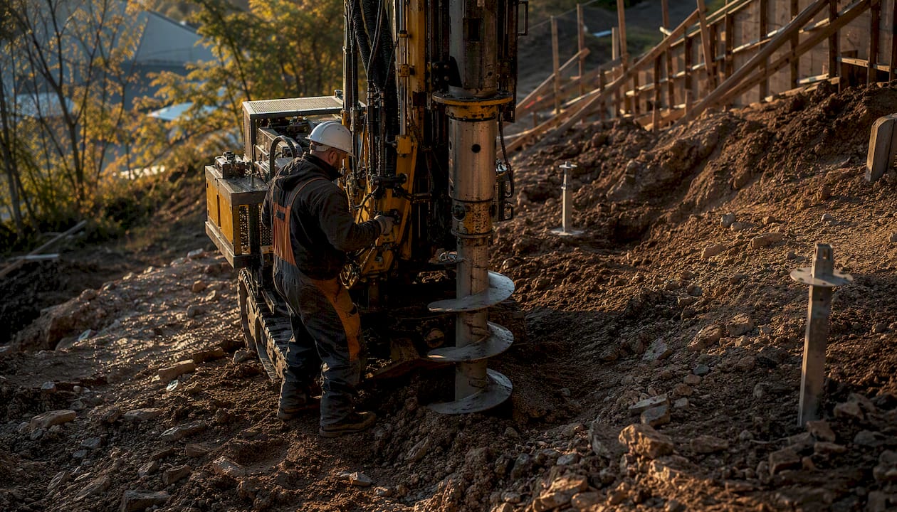
Helical piles, also called screw piles or helical piers, are steel shafts fitted with one or more helix-shaped bearing plates that are rotated into the ground using a hydraulic drive head. The installation torque measured during screwing correlates directly to the pile’s bearing capacity, giving the engineer a real-time, field-verifiable load estimate without waiting for concrete to cure. That capacity correlation is one of the method’s most practical advantages on time-sensitive projects.
Installation sequence:
- Site preparation and layout: mark pile locations per the engineer’s plan.
- Positioning: set the hydraulic drive head on the lead section of the helical shaft.
- Screwing-in: rotate the shaft under controlled torque, adding extension sections until the target depth and torque are reached.
- Bracket attachment: connect a steel bracket or cap plate to the pile head, then transfer the existing footing load onto the bracket using hydraulic jacks.
- Load verification: confirm torque readings against the engineer’s acceptance criteria before releasing temporary support.
Pro Tip: Ask the installer to provide a continuous torque log for every pile. That log is your field record of capacity, and it should be reviewed by the engineer of record before any temporary support is removed.
Helical piles perform best in cohesive or moderately dense granular soils where the helix plates can develop bearing. They are less effective in very dense gravels or cobble-rich soils where the plates cannot advance cleanly, and in very soft clays where torque readings may underestimate long-term capacity due to soil disturbance. They are also limited in the total axial load they can carry compared with large-diameter drilled shafts or micropiles, making them better suited to residential and light commercial structures than to heavily loaded commercial or industrial foundations. Their low vibration profile and immediate load transfer after installation make them a preferred choice on sites adjacent to sensitive structures or where excavation must be minimized.
What are the differences between grout injection, resin injection, and jet grouting?
These three methods are grouped together in many project discussions, but they solve different problems and carry very different load-transfer capabilities. Understanding the distinction prevents costly misapplication.
Pressure / chemical grouting involves injecting a cementitious or chemical grout at low to moderate pressure into voids, fissures, or granular soils. The grout fills open spaces and, in granular soils, permeates the pore structure to increase stiffness. It is most effective for void filling beneath slabs, stabilizing loose sands, and arresting active settlement caused by subsurface erosion or sinkhole activity.
Polyurethane resin injection uses a two-component expanding resin that fills voids and can produce a controlled, measurable lift of settled slabs. The process is fast, minimally disruptive, and well-suited to commercial floor slabs, highway pavements, and residential concrete flatwork. However, resin injection does not provide the verified, high-capacity load path that structural piles deliver, and it should not be used as a substitute for structural underpinning when significant foundation loads need to be transferred to deeper strata.
Jet grouting operates on a fundamentally different principle. A high-pressure fluid jet cuts and mixes the in-situ soil with a cementitious grout to form soilcrete columns. These columns can be designed to carry structural loads, act as a groundwater barrier, or improve soil stiffness across a zone. Jet grouting is used where mechanical piles are impractical due to obstructions, contaminated ground, or geometric constraints, and it requires specialist equipment and careful post-installation verification.
Key distinctions:
- Resin and pressure grouting: best for void fill, minor lift, and granular soil stabilization; not a structural pile substitute.
- Jet grouting: forms load-bearing soilcrete columns; requires specialist rigs and post-treatment verification.
- All injection methods require post-installation monitoring, typically settlement monitoring points and, for jet grouting, core sampling or integrity testing to confirm column geometry and strength.
- Environmental review is required before any chemical grout or resin is injected near groundwater, as contamination risk must be assessed and documented.
How does a professional engineer select the right underpinning method?
Engineers select an underpinning method by evaluating soil profile, depth to competent strata, structural loads, site access, water table depth, and permitted working methods. No single factor dominates; the decision is a matrix of constraints. A geotechnical investigation is the non-negotiable starting point because the soil data drives every subsequent decision.
Engineering and geotechnical checklist:
- Geotechnical borings with Standard Penetration Test (SPT) or Cone Penetration Test (CPT) data to characterize soil layers and identify the bearing stratum.
- Laboratory tests for soil classification, shear strength, and compressibility where settlement is the primary concern.
- Structural load calculations for the existing footing, including dead load, live load, and any eccentric or lateral components.
- Lateral earth pressure analysis and temporary support design for any excavation-based method.
- Sequence-of-work drawing that shows bay order, temporary propping, and load transfer steps.
- Instrumentation and monitoring plan: settlement points, inclinometers, and crack monitors where adjacent structures or utilities are at risk.
- Building permit category and local inspection schedule, confirmed with the authority having jurisdiction (AHJ).
The table below compares the main underpinning methods across the dimensions most relevant to method selection.
| Method | Best for | Depth / load capacity | Access / disruption | Relative cost | Speed | Soil limitations |
|---|---|---|---|---|---|---|
| Mass concrete (pit) | Shallow foundations, good soil slightly deeper | Shallow; moderate loads | High disruption; open excavation | Low | Slow (curing) | Ineffective in high water table or deep weak soils |
| Beam-and-base | Continuous walls, heavier/variable loads | Shallow to moderate | High disruption; less excavation than pit | Low–Medium | Slow (curing) | Similar to mass concrete |
| Mini-piles / micropiles | Deep bearing, restricted access, heritage | Deep (15 m+); high axial capacity | Medium; compact rigs | Medium–High | Moderate | Requires grout bond; sensitive to artesian conditions |
| Pile-and-beam | Weak surface soils, heavy loads | Deep; high capacity | Medium | Medium–High | Moderate | Driven variants limited by obstructions |
| Helical piles | Light–medium loads, low vibration, fast install | Moderate depth; light–medium loads | Low–Medium; minimal excavation | Medium | Fast | Poor in dense gravel or very soft clay |
| Push / pier systems | Residential/light commercial settlement | Moderate–deep; light–medium loads | Low–Medium | Medium | Fast | Requires refusal layer |
| Jet grouting | Obstructed or contaminated sites, soil improvement | Variable; structural columns possible | Medium; specialist equipment | High | Moderate | Requires post-treatment verification |
| Resin / pressure grouting | Void fill, minor slab lift, granular stabilization | Shallow; not a pile substitute | Low | Low–Medium | Fast | Not suitable for high structural loads |
Questions to ask your engineer or contractor:
- “What geotechnical data supports this method choice, and can I see the bore logs?”
- “How will load transfer be verified during and after installation?”
- “Who signs and stamps the calculations, and are they licensed in this state?”
- “What is the instrumentation plan for adjacent structures?”
Stamped PE designs, a building department permit, and a documented inspection schedule are the minimum trust signals for any underpinning project in the United States. Jurisdictions such as New York City impose additional requirements, including lateral-load analyses and sequencing drawings, as part of the permit package.
What disruption, timeline, and cost should you expect from underpinning?
Cost and disruption scale together, but not always in the direction property owners expect. Shallow mass concrete underpinning carries the lowest material cost but the highest excavation footprint, the longest cure-driven timeline, and the greatest occupant impact. Deep piling and jet grouting carry higher unit costs but a smaller excavation footprint and, in many cases, faster overall project delivery once equipment is mobilized.
Relative cost and disruption by method group:
- Low cost, high disruption: Mass concrete and beam-and-base. Excavation is extensive, occupants must vacate affected areas, and the project timeline is governed by concrete cure cycles, typically several weeks for a modest residential job.
- Medium cost, medium disruption: Mini-piles, micropiles, pile-and-beam, helical piles, and push piers. Specialist equipment adds cost, but the excavation footprint is smaller and installation is faster once the rig is on site.
- High cost, lower excavation footprint: Jet grouting and compaction grouting. Equipment mobilization and post-treatment verification drive cost, but surface disruption is limited.
- Low cost, low disruption: Resin and pressure grouting for void fill. Fast and minimally invasive, but only appropriate for the specific problems these methods address.
Timeline drivers include permitting (which can add weeks in jurisdictions with detailed review requirements), geotechnical investigation and reporting, equipment mobilization for specialist methods, staged excavation and curing cycles, and weather. A residential mass concrete underpinning project might run 4–8 weeks from permit to completion; a micropile project on a commercial building could extend to several months when investigation, design, permitting, and installation are counted together.
Budgeting advice:
- Include a contingency allowance for unexpected soil conditions encountered during excavation or drilling, which is one of the most common sources of cost overrun on underpinning projects.
- Budget for third-party inspection and monitoring, particularly where adjacent structures or utilities are at risk.
- Confirm whether environmental controls (dewatering, contaminated soil disposal) are required before fixing a cost estimate.
- Avoid fixed-price bids that do not include a site investigation phase; a contractor pricing without soil data is pricing without the information needed to do so accurately.
Which underpinning method fits common real-world scenarios?
Three scenario sketches illustrate how the method selection logic plays out in practice.
Scenario 1: Older low-rise home with shallow settlement, good soil 1.5–2 m below grade
An older single-story residence shows differential settlement at a corner, with crack patterns consistent with footing movement rather than superstructure distress. Borings confirm a stiff clay or dense sand layer within 2 m of the existing footing base. Mass concrete underpinning or beam-and-base is the appropriate choice: the bearing stratum is accessible by hand excavation, material costs are low, and the method is well within the capability of most licensed foundation contractors. The primary risk is inadequate bay sequencing; the engineer must specify the exact order of excavation and the temporary wedging detail at each bay.
Scenario 2: Urban townhouse with deep soft soils and restricted side access
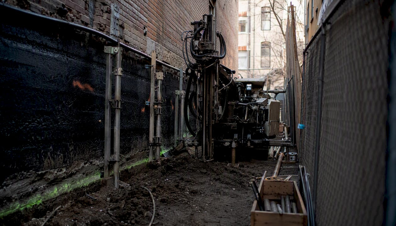
A three-story masonry townhouse in a dense urban block shows progressive settlement due to soft compressible fill extending 6–8 m below grade. Side access is limited to a 900 mm passage. Mini-piles or micropiles are the correct answer: compact drilling rigs can work within the access constraint, the piles reach the bearing stratum below the soft fill, and vibration is low enough to protect the adjacent party wall. The risk to watch for is grout quality control; a poorly grouted pile will not develop its design capacity, and integrity testing should be specified.
Scenario 3: Commercial slab settlement with voids beneath
A warehouse floor slab shows 30–50 mm of differential settlement, and ground-penetrating radar confirms voids beneath the slab caused by subsurface erosion. Resin injection or compaction grouting is appropriate for void filling and slab lift, combined with settlement monitoring points to verify stability after treatment. The critical risk is misidentifying the cause: if the voids are caused by ongoing subsurface erosion rather than a one-time event, injection alone will not prevent recurrence, and the source of erosion must be addressed separately.
Pro Tip: Hybrid solutions are more common than single-method projects on complex sites. A pile-plus-beam arrangement combined with resin void fill beneath the slab, for example, addresses both load transfer and immediate slab stability in one coordinated scope. Ask the engineer whether a combined approach reduces overall risk before committing to a single method.
What permits, contractor credentials, and risks apply in the US?
Underpinning is a permanent structural modification. In the United States, it requires a building department permit in virtually every jurisdiction, and the permit package must include stamped PE designs that address the method, sequence, load transfer, lateral earth pressures, and monitoring requirements. Many jurisdictions also require a special inspection program, meaning a third-party inspector must be present during critical installation phases and must document compliance with the approved drawings.
Contractor credential checklist:
- State contractor’s license with a structural or foundation specialty classification where required by the jurisdiction.
- General liability insurance and contractor’s bonding, with certificates naming the property owner.
- References from completed underpinning projects of similar scope and method, with contact details for verification.
- Documented instrumentation plan showing settlement monitoring points, crack monitors, and reporting frequency.
- Sequence-of-work drawings prepared or reviewed by the engineer of record, not just the contractor.
Red flags to watch for:
- No staged-sequence drawings in the permit package.
- No soil investigation data supporting the method choice.
- Missing or vague instrumentation plan.
- A fixed-price bid submitted before any site investigation has been completed.
- Pressure to begin work before the permit is issued.
Jurisdictional requirements vary significantly. New York City, for example, requires sequencing drawings and lateral-load analyses as part of the underpinning permit package, and inspections are mandatory at defined stages. Other municipalities may have less prescriptive requirements, but the engineering obligations do not diminish simply because local enforcement is lighter. Confirming the local building-code triggers with the AHJ before design begins is a standard step in responsible project management.
Key Takeaways
Matching the underpinning method to soil conditions, depth to bearing strata, structural loads, and site access is the single most consequential decision in any foundation repair or strengthening project, and it cannot be made without a geotechnical investigation and stamped PE designs.
| Point | Details |
|---|---|
| Match method to soil and access | Mass concrete suits shallow bearing; micropiles and helical piles address deep strata or restricted access. |
| Geotechnical data is non-negotiable | SPT/CPT borings and lab tests must precede method selection; pricing without soil data is unreliable. |
| Stamped designs and monitoring are required | US building departments require PE-stamped drawings, permits, and third-party inspection for underpinning works. |
| Budget for contingency | Unexpected soil conditions and environmental controls are the most common sources of cost overrun; include a contingency allowance. |
| Aectechnicalsg for engineering consultancy | Aectechnicalsg provides structural and geotechnical engineering consultancy, including stamped design and authority submission support for underpinning and foundation projects. |
Why sequencing and soil data matter more than method choice
The conventional wisdom in foundation repair discussions tends to focus on which underpinning method is “best,” as though the method itself is the primary variable. That framing misses the point. The method is almost always secondary to the quality of the geotechnical data and the rigor of the sequence-of-work design.
A correctly selected method executed with poor sequencing will cause more damage than a conservatively selected method executed with discipline. The NYC Buildings Department’s underpinning guidance makes this explicit: lateral earth pressures, temporary support details, and staged bay sequencing are design requirements, not site-level judgment calls. Engineers who treat sequencing as a contractor’s problem rather than a design deliverable are transferring risk to the structure and the occupants.
The second underestimated variable is the geotechnical investigation itself. A single borehole at the center of a site will not capture the variability that drives method selection at the corners and edges. Specifying a minimum investigation scope that matches the spatial extent of the underpinning works is a basic professional obligation, yet it is frequently compressed to reduce pre-design costs. That compression almost always costs more in remedial work than it saves in investigation fees.
For any project involving underpinning, the first question on day one of site investigation should be: “Show me the bore log locations relative to the proposed underpinning footprint, and show me the proposed load path verification plan.” If those two documents do not exist at the start of the investigation, the project is not ready to proceed.
Useful sources for further reading on underpinning
The following references provide authoritative technical detail and code-level guidance for readers who need to go deeper on specific methods or regulatory requirements.
- NYSSPE Presentation Underpinning
- Concrete Foundation Underpinning: Methods, Cost & Process
- Foundation Underpinning: Methods, Applications, and Contractor Selection | Foundation Authority
- Underpin
- Foundation Underpinning Methods | Modern Stabilization Solutions
- Underpinning (Darda knowledge base)
Local building department code provisions and the International Building Code (IBC) chapters covering foundations and special inspections should also be consulted for jurisdiction-specific requirements. Final decisions on method selection and design must be confirmed with a licensed professional engineer.
This article provides general technical information for educational purposes. It is not a substitute for professional engineering advice. Confirm all design, permitting, and inspection requirements with a licensed structural or geotechnical engineer and the authority having jurisdiction.
Aectechnicalsg brings engineering expertise to your underpinning project
Foundation underpinning is not a project to manage with a general contractor and a generic specification. The soil data, load path verification, sequence drawings, and permit submissions all require a qualified structural and geotechnical engineer who understands both the technical requirements and the regulatory framework.

Aectechnicalsg provides structural and geotechnical engineering consultancy for foundation repair and strengthening projects, including underpinning design, PE endorsement and authority submissions, and full project documentation. The team works with property developers, construction firms, and building owners who need technically rigorous, compliant engineering solutions rather than generic contractor advice. If your project requires stamped calculations, a sequence-of-work design, or support navigating the permit process, contact Aectechnicalsg to discuss the scope and commission the geotechnical and structural assessment your project needs.